Product Description
Product Description
Product Features
High modular design, biomimetic surface with owned intellectual property right.
Adopt German worm hob to process the worm wheel.
With the special gear geometry, it gets high torque, efficiency and long life circle.
It can achieve the direct combination for 2 sets of gearbox.
Mounting mode: foot mounted, flange mounted, torque arm mounted.
Output shaft: CZPT shaft, hollow shaft.
Main applied for
Chemical industry and environmental protection
Metal processing
Building and construction
Agriculture and food
Textile and leather
Forest and paper
Car washing machinery
Detailed Photos
Product Parameters
Technical data:
|
Housing material |
Cast iron/Ductile iron |
|
Housing hardness |
HBS190-240 |
|
Gear material |
20CrMnTi alloy steel |
|
Surface hardness of gears |
HRC58°~62 ° |
|
Gear core hardness |
HRC33~40 |
|
Input / Output shaft material |
42CrMo alloy steel |
|
Input / Output shaft hardness |
HRC25~30 |
|
Machining precision of gears |
accurate grinding, 6~5 Grade |
|
Lubricating oil |
GB L-CKC220-460, Shell Omala220-460 |
|
Heat treatment |
tempering, cementiting, quenching, etc. |
|
Efficiency |
94%~96% (depends on the transmission stage) |
|
Noise (MAX) |
60~68dB |
|
Temp. rise (MAX) |
40°C |
|
Temp. rise (Oil)(MAX) |
50°C |
|
Vibration |
≤20µm |
|
Backlash |
≤20Arcmin |
|
Brand of bearings |
China top brand bearing, HRB/LYC/ZWZ/C&U. Or other brands requested, SKF, FAG, INA, NSK. |
|
Brand of oil seal |
CZPT — ZheJiang or other brands requested |
Our Advantages
Certifications
Packaging & Shipping
Company Profile
Xihu (West Lake) Dis.ng Transmission Equipment Co., Ltd. located HangZhou city, ZHangZhoug, as 1 professional manufacturer and exporter of cycloidal pin wheel reducer,worm reducer, gear reducer, gearbox , AC motor and relative spare parts, owns rich experience in this line for many years.
We are 1 direct factory, with advanced production equipment, the strong development team and producing capacity to offer quality products for customers.
Our products widely served to various industries of Metallurgy, Chemicals, lifting,mining,Petroleum,textile,medicine,wooden etc. Main markets: China, Africa,Australia,Vietnam, Turkey,Japan, Korea, Philippines…
Welcome to ask us any questions, good offer always for you for long term business.
FAQ
Q: Are you trading company or manufacturer?
A: We are factory.
Q: How long is your delivery time?
A: Generally it is 5-10 days if the goods are in stock. or it is 15-20 days if the goods are not in stock.
Q: Can we buy 1 pc of each item for quality testing?
A: Yes, we are glad to accept trial order for quality testing.
Q:How to choose a gearbox which meets your requirement?
A:You can refer to our catalogue to choose the gearbox or we can help to choose when you provide
the technical information of required output torque, output speed and motor parameter etc.
Q: What information shall we give before placing a purchase order?
A:a) Type of the gearbox, ratio, input and output type, input flange, mounting position, and motor informationetc.
b) Housing color.
c) Purchase quantity.
d) Other special requirements.
/* January 22, 2571 19:08:37 */!function(){function s(e,r){var a,o={};try{e&&e.split(“,”).forEach(function(e,t){e&&(a=e.match(/(.*?):(.*)$/))&&1
| Application: | Motor, Machinery, Marine, Agricultural Machinery |
|---|---|
| Hardness: | Hardened Tooth Surface |
| Installation: | 90 Degree |
| Layout: | Coaxial |
| Gear Shape: | Worm Gear |
| Step: | Single-Step |
Agricultural Gearboxes
There are several types of agricultural gearboxes, and they are used in various applications. Among them are Bevel gearboxes, CZPT speed gearboxes, and Worm gear speed reducers. If you’re looking for a reliable, high-performing agricultural gearbox, you’ve come to the right place. Read on to learn more about these gearboxes. Also, check out our guide to bevel gearboxes.
Bevel gearboxes
The fatigue life of bevel gearboxes in agricultural equipment is determined by the cumulative damage sums for different operations. A simulation model was used to assess the fatigue life of a spiral bevel gear. The accumulated damage sums for each operation were shown in figure 9a. The subsoiler tillage operation exceeded the damage sum of one. This criterion indicates that the fatigue life of a gearbox is shorter than its service life.
In bevel gearboxes, the second shaft has two shafts that are connected to each other. One shaft is mounted to the outer surface of the housing 3 through bearings, while the other shaft has a flange that protrudes into the gear housing. The second shaft is attached via bearings on the gear housing and flange. It is mounted in this way to allow the bevel gear to rotate smoothly.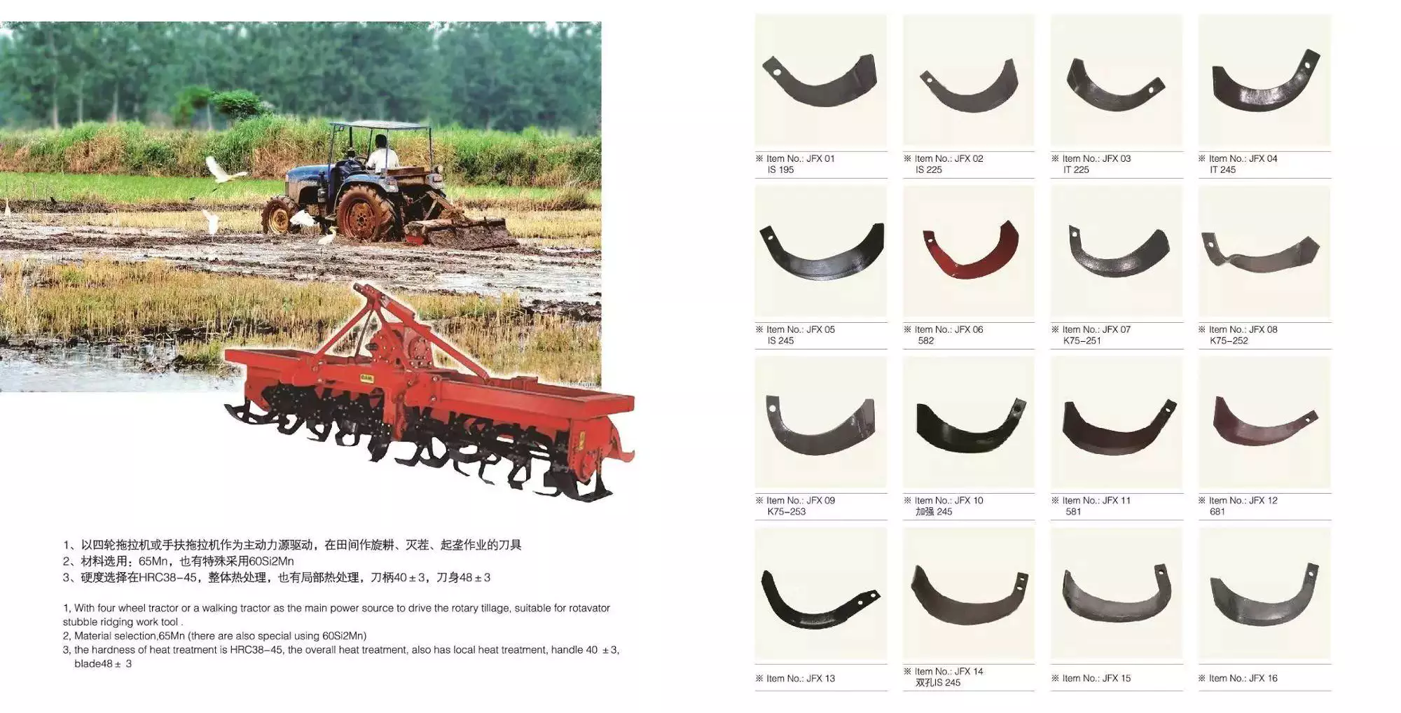
CZPT speed gearboxes
If you are an agricultural machine owner, you know that the right speed agricultural gearboxes can make the difference between a profitable crop harvest or a disaster. Today’s agricultural machinery can be found in a variety of applications, including for crop and animal production. Many of these applications require heavy-duty gearboxes with large capacity. The quality of these agricultural gearboxes depends on the quality of their bearings, which are important to the longevity of your equipment.
Industrial CZPT gearboxes can be repaired and overhauled by qualified and experienced technicians at CZPT Products. CZPT gearboxes can be repaired or rebuilt at significant savings. For industrial uses, the RAR model is perfect for applications where space is a consideration. Industrial CZPT gearboxes are available in multiple sizes and types, and they can be customized to meet your unique needs. For the best price and service, contact CZPT Products today!
CZPT speed bevel gearboxes
The demand for food has skyrocketed since the 2010 global financial crisis, and while the world’s population is still rising, at a slower rate, land is not. This is forcing agricultural machinery manufacturers to come up with innovative solutions to maximize the use of available land. The need for agricultural machinery is also growing due to shorter cropping cycles and wear and tear on equipment. CZPT gearbox manufacturers are meeting this demand with high-quality products.
A number of benefits make CZPT speed bevel gearboxes the preferred choice for agricultural applications. In addition to its renowned performance, the product’s design has been adapted for use in agricultural and glass machinery. The result is a unit with low backlash and high transmission. Moreover, the CZPT model is the best all-rounder among servo right-angle gearboxes.
editor by Dream 2024-04-29
China supplier Right Angle Durable Hardened Hypoid Gear Motor Gearbox with Hollow Shaft agricultural machinery gearboxes
Product Description
Product Description
KPM-KPB series helical-hypoid gearboxes are the new-generation product with a compromise of advanced technology both at home and abroad.This product is widely used in textile, foodstuff, beverage,tobacco, logistics industrial fields,etc.
Main Features:
(1) Driven by hypoid gears, which has big ratios.
(2) Large output torque, high efficiency(up to 92%), energy saving and environmental protection.
(3) High quality aluminum alloy housing, light in weight and non-rusting.
(4) Smooth in running and low in noise, and can work long time in dreadful conditions.
(5) Good-looking appearance, durable service life and small volume.
(6) Suitable for all round installation, wide application and easy use.
(7) KPM series can replace NMRV worm gearbox; KPB series can replace CZPT W series worm gearbox;
(8) Modular and multi-structure can meet the demands of various conditions.
Main Material:
(1) Housing: aluminum alloy
(2) Gear wheel: 20CrMnTiH1,carbonize & quencher heat treatment make the hardness of gears surface up to 56-62 HRC, retain carburization layers thickness between 0.3 and 0.5mm after precise grinding.
Detailed Photos
Product Parameters
Model Information:
| GEARBOX SELECTING TABLES | ||||||||||||
| KPM50.. | n1=1400r/min | 160Nm | ||||||||||
| Model | i | i | n2 | M2max | Fr2 | 63B5 | 71B5/B14 | 80B5/B14 | 90B5/B14 | |||
| nominal | actual | [r/min] | [Nm] | [N] | ||||||||
| 3 Stage | ||||||||||||
| KPM50C | 300 | 294.05 | 4.8 | 130 | 4100 | N/A | N/A | N/A | ||||
| KPM50C | 250 | 244.29 | 5.8 | 130 | 4100 | N/A | N/A | N/A | ||||
| KPM50C | 200 | 200.44 | 7.0 | 130 | 4100 | N/A | N/A | N/A | ||||
| KPM50C | 150 | 146.67 | 9.6 | 160 | 4000 | N/A | N/A | N/A | ||||
| KPM50C | 125 | 120.34 | 12 | 160 | 3770 | N/A | N/A | |||||
| KPM50C | 100 | 101.04 | 14 | 160 | 3560 | N/A | N/A | |||||
| KPM50C | 75 | 74.62 | 19 | 160 | 3220 | N/A | N/A | |||||
| KPM50C | 60 | 62.36 | 23 | 160 | 3030 | N/A | N/A | |||||
| KPM50C | 50 | 52.36 | 27 | 160 | 2860 | N/A | N/A | |||||
| 2 Stage | ||||||||||||
| KPM50B | 60 | 58.36 | 24 | 130 | 2960 | N/A | N/A | |||||
| KPM50B | 50 | 48.86 | 29 | 130 | 2790 | N/A | ||||||
| KPM50B | 40 | 40.09 | 35 | 130 | 2610 | N/A | ||||||
| KPM50B | 30 | 29.33 | 48 | 160 | 2350 | N/A | ||||||
| KPM50B | 25 | 24.07 | 59 | 160 | 2200 | |||||||
| KPM50B | 20 | 20.21 | 70 | 160 | 2080 | |||||||
| KPM50B | 15 | 14.92 | 94 | 160 | 1880 | |||||||
| KPM50B | 12.5 | 12.47 | 113 | 160 | 1770 | |||||||
| KPM50B | 10 | 10.47 | 134 | 160 | 1670 | |||||||
| KPM50B | 7.5 | 7.73 | 182 | 160 | 1510 | |||||||
| KPM63..,KPB63.. | n1=1400r/min | 180Nm | ||||||||||
| Model | i | i | n2 | M2max | Fr2 | 63B5 | 71B5/B14 | 80B5/B14 | 90B5/B14 | |||
| nominal | actual | [r/min] | [Nm] | [N] | ||||||||
| 3 Stage | ||||||||||||
| KPM63C | KPB63C | 300 | 302.50 | 4.7 | 160 | 4800 | N/A | N/A | N/A | |||
| KPM63C | KPB63C | 250 | 243.57 | 5.8 | 160 | 4800 | N/A | N/A | N/A | |||
| KPM63C | KPB63C | 200 | 196.43 | 7.2 | 160 | 4800 | N/A | N/A | ||||
| KPM63C | KPB63C | 150 | 151.56 | 9.3 | 180 | 4650 | N/A | N/A | ||||
| KPM63C | KPB63C | 125 | 122.22 | 12 | 180 | 4330 | N/A | N/A | ||||
| KPM63C | KPB63C | 100 | 94.50 | 14 | 180 | 4070 | N/A | N/A | ||||
| KPM63C | KPB63C | 75 | 73.33 | 20 | 180 | 3650 | N/A | |||||
| KPM63C | KPB63C | 60 | 63.33 | 23 | 180 | 3480 | N/A | |||||
| KPM63C | KPB63C | 50 | 52.48 | 27 | 180 | 3270 | N/A | |||||
| 2 Stage | ||||||||||||
| KPM63B | KPB63B | 60 | 60.50 | 24 | 160 | 3430 | N/A | |||||
| KPM63B | KPB63B | 50 | 48.71 | 29 | 160 | 3190 | ||||||
| KPM63B | KPB63B | 40 | 39.29 | 36 | 160 | 2970 | ||||||
| KPM63B | KPB63B | 30 | 30.31 | 47 | 180 | 2720 | ||||||
| KPM63B | KPB63B | 25 | 24.44 | 58 | 180 | 2530 | N/A | |||||
| KPM63B | KPB63B | 20 | 18.90 | 70 | 180 | 2380 | N/A | |||||
| KPM63B | KPB63B | 15 | 14.67 | 96 | 180 | 2130 | N/A | N/A | ||||
| KPM63B | KPB63B | 12.5 | 12.67 | 111 | 180 | 2030 | N/A | N/A | ||||
| KPM63B | KPB63B | 10 | 10.50 | 134 | 180 | 1910 | N/A | N/A | ||||
| KPM63B | KPB63B | 7.5 | 7.60 | 185 | 180 | 1710 | N/A | N/A | ||||
| KPM75..,KPB75.. | n1=1400r/min | 350Nm | ||||||||||
| Model | i | i | n2 | M2max | Fr2 | 63B5 | 71B5 | 80B5/B14 | 90B5/B14 | 100B5/B14 | 112B5/B14 | |
| nominal | actual | [r/min] | [Nm] | [N] | ||||||||
| 3 Stage | ||||||||||||
| KPM75C | KPB75C | 300 | 297.21 | 4.8 | 300 | 6500 | N/A | N/A | N/A | N/A | ||
| KPM75C | KPB75C | 250 | 240.89 | 5.9 | 300 | 6500 | N/A | N/A | N/A | N/A | ||
| KPM75C | KPB75C | 200 | 200.66 | 7.0 | 300 | 6500 | N/A | N/A | N/A | N/A | ||
| KPM75C | KPB75C | 150 | 149.30 | 9.3 | 350 | 6500 | N/A | N/A | N/A | |||
| KPM75C | KPB75C | 125 | 121.00 | 12 | 350 | 5980 | N/A | N/A | N/A | |||
| KPM75C | KPB75C | 100 | 100.80 | 15 | 350 | 5520 | N/A | N/A | N/A | |||
| KPM75C | KPB75C | 75 | 79.40 | 19 | 350 | 5040 | N/A | N/A | ||||
| KPM75C | KPB75C | 60 | 62.43 | 23 | 350 | 4730 | N/A | N/A | N/A | |||
| KPM75C | KPB75C | 50 | 49.18 | 29 | 350 | 4370 | N/A | N/A | N/A | |||
| 2 Stage | ||||||||||||
| KPM75B | KPB75B | 60 | 59.44 | 24 | 300 | 4660 | N/A | N/A | N/A | |||
| KPM75B | KPB75B | 50 | 48.18 | 30 | 300 | 4340 | N/A | N/A | N/A | |||
| KPM75B | KPB75B | 40 | 40.13 | 35 | 300 | 4080 | N/A | N/A | ||||
| KPM75B | KPB75B | 30 | 29.86 | 47 | 350 | 3720 | N/A | N/A | N/A | |||
| KPM75B | KPB75B | 25 | 24.20 | 56 | 350 | 3500 | N/A | N/A | ||||
| KPM75B | KPB75B | 20 | 20.16 | 71 | 350 | 3230 | N/A | N/A | ||||
| KPM75B | KPB75B | 15 | 15.88 | 93 | 350 | 2950 | N/A | N/A | ||||
| KPM75B | KPB75B | 12.5 | 12.49 | 113 | 350 | 2770 | N/A | N/A | N/A | |||
| KPM75B | KPB75B | 10 | 9.84 | 143 | 350 | 2550 | N/A | N/A | N/A | |||
| KPM75B | KPB75B | 7.5 | 7.48 | 188 | 350 | 2330 | N/A | N/A | N/A | |||
| KPM90..,KPB86.. | n1=1400r/min | 500Nm | ||||||||||
| Model | i | i | n2 | M2max | Fr2 | 63B5 | 71B5 | 80B5/B14 | 90B5/B14 | 100B5/B14 | 112B5/B14 | |
| nominal | actual | [r/min] | [Nm] | [N] | ||||||||
| 3 Stage | ||||||||||||
| KPM90C | KPB86C | 300 | 297.21 | 4.8 | 450 | 6500 | N/A | N/A | N/A | N/A | ||
| KPM90C | KPB86C | 250 | 240.89 | 5.9 | 450 | 6500 | N/A | N/A | N/A | |||
| KPM90C | KPB86C | 200 | 200.66 | 7.0 | 450 | 6500 | N/A | N/A | N/A | |||
| KPM90C | KPB86C | 150 | 151.20 | 9.3 | 500 | 6500 | N/A | N/A | N/A | |||
| KPM90C | KPB86C | 125 | 125.95 | 12 | 500 | 5980 | N/A | N/A | N/A | |||
| KPM90C | KPB86C | 100 | 99.22 | 15 | 500 | 5520 | N/A | N/A | N/A | |||
| KPM90C | KPB86C | 75 | 75.45 | 19 | 500 | 5040 | N/A | N/A | N/A | |||
| KPM90C | KPB86C | 60 | 62.43 | 23 | 500 | 4730 | N/A | N/A | N/A | |||
| KPM90C | KPB86C | 50 | 49.18 | 29 | 500 | 4370 | N/A | N/A | N/A | |||
| 2 Stage | ||||||||||||
| KPM90B | KPB86B | 60 | 59.44 | 24 | 450 | 5890 | N/A | N/A | ||||
| KPM90B | KPB86B | 50 | 48.18 | 30 | 450 | 5500 | N/A | N/A | ||||
| KPM90B | KPB86B | 40 | 40.13 | 35 | 450 | 5170 | N/A | N/A | ||||
| KPM90B | KPB86B | 30 | 30.24 | 47 | 500 | 4710 | N/A | N/A | ||||
| KPM90B | KPB86B | 25 | 25.19 | 56 | 500 | 4430 | N/A | N/A | ||||
| KPM90B | KPB86B | 20 | 19.84 | 71 | 500 | 4090 | N/A | N/A | N/A | |||
| KPM90B | KPB86B | 15 | 15.09 | 93 | 500 | 3730 | N/A | N/A | N/A | |||
| KPM90B | KPB86B | 12.5 | 12.49 | 113 | 500 | 3510 | N/A | N/A | N/A | |||
| KPM90B | KPB86B | 10 | 9.84 | 143 | 500 | 3240 | N/A | N/A | N/A | |||
| KPM90B | KPB86B | 7.5 | 7.48 | 188 | 500 | 2950 | N/A | N/A | N/A | |||
Outline Dimension:
Company Profile
About our company:
We are a professional reducer manufacturer located in HangZhou, ZHangZhoug province.Our leading products is full range of RV571-150 worm reducers , also supplied hypoid helical gearbox, PC units, UDL Variators and AC Motors.Products are widely used for applications such as: foodstuffs, ceramics, packing, chemicals, pharmacy, plastics, paper-making, construction machinery, metallurgic mine, environmental protection engineering, and all kinds of automatic lines, and assembly lines.With fast delivery, superior after-sales service, advanced producing facility, our products sell well both at home and abroad. We have exported our reducers to Southeast Asia, Eastern Europe and Middle East and so on.Our aim is to develop and innovate on basis of high quality, and create a good reputation for reducers.
Packing information:Plastic Bags+Cartons+Wooden Cases , or on request
We participate Germany Hannver Exhibition-ZheJiang PTC Fair-Turkey Win Eurasia
Logistics
After Sales Service
1.Maintenance Time and Warranty:Within 1 year after receiving goods.
2.Other Service: Including modeling selection guide, installation guide, and problem resolution guide, etc.
FAQ
1.Q:Can you make as per customer drawing?
A: Yes, we offer customized service for customers accordingly. We can use customer’s nameplate for gearboxes.
2.Q:What is your terms of payment ?
A: 30% deposit before production,balance T/T before delivery.
3.Q:Are you a trading company or manufacturer?
A:We are a manufacurer with advanced equipment and experienced workers.
4.Q:What’s your production capacity?
A:8000-9000 PCS/MONTH
5.Q:Free sample is available or not?
A:Yes, we can supply free sample if customer agree to pay for the courier cost
6.Q:Do you have any certificate?
A:Yes, we have CE certificate and SGS certificate report.
Contact information:
Ms Lingel Pan
For any questions just feel free ton contact me. Many thanks for your kind attention to our company!
| Application: | Motor, Machinery, Marine, Agricultural Machinery, Industry |
|---|---|
| Function: | Distribution Power, Change Drive Torque, Change Drive Direction, Speed Changing, Speed Reduction |
| Layout: | Right-Angle |
| Hardness: | Hardened Tooth Surface |
| Installation: | Horizontal Type |
| Step: | Two Stage-Three Stage |
| Samples: |
US$ 45/Piece
1 Piece(Min.Order) | |
|---|
| Customization: |
Available
| Customized Request |
|---|
Agricultural Gearboxes
There are several types of agricultural gearboxes, and they are used in various applications. Among them are Bevel gearboxes, CZPT speed gearboxes, and Worm gear speed reducers. If you’re looking for a reliable, high-performing agricultural gearbox, you’ve come to the right place. Read on to learn more about these gearboxes. Also, check out our guide to bevel gearboxes.
Bevel gearboxes
The fatigue life of bevel gearboxes in agricultural equipment is determined by the cumulative damage sums for different operations. A simulation model was used to assess the fatigue life of a spiral bevel gear. The accumulated damage sums for each operation were shown in figure 9a. The subsoiler tillage operation exceeded the damage sum of one. This criterion indicates that the fatigue life of a gearbox is shorter than its service life.
In bevel gearboxes, the second shaft has two shafts that are connected to each other. One shaft is mounted to the outer surface of the housing 3 through bearings, while the other shaft has a flange that protrudes into the gear housing. The second shaft is attached via bearings on the gear housing and flange. It is mounted in this way to allow the bevel gear to rotate smoothly.
CZPT speed gearboxes
If you are an agricultural machine owner, you know that the right speed agricultural gearboxes can make the difference between a profitable crop harvest or a disaster. Today’s agricultural machinery can be found in a variety of applications, including for crop and animal production. Many of these applications require heavy-duty gearboxes with large capacity. The quality of these agricultural gearboxes depends on the quality of their bearings, which are important to the longevity of your equipment.
Industrial CZPT gearboxes can be repaired and overhauled by qualified and experienced technicians at CZPT Products. CZPT gearboxes can be repaired or rebuilt at significant savings. For industrial uses, the RAR model is perfect for applications where space is a consideration. Industrial CZPT gearboxes are available in multiple sizes and types, and they can be customized to meet your unique needs. For the best price and service, contact CZPT Products today!
CZPT speed bevel gearboxes
The demand for food has skyrocketed since the 2010 global financial crisis, and while the world’s population is still rising, at a slower rate, land is not. This is forcing agricultural machinery manufacturers to come up with innovative solutions to maximize the use of available land. The need for agricultural machinery is also growing due to shorter cropping cycles and wear and tear on equipment. CZPT gearbox manufacturers are meeting this demand with high-quality products.
A number of benefits make CZPT speed bevel gearboxes the preferred choice for agricultural applications. In addition to its renowned performance, the product’s design has been adapted for use in agricultural and glass machinery. The result is a unit with low backlash and high transmission. Moreover, the CZPT model is the best all-rounder among servo right-angle gearboxes.
editor by CX 2023-05-29
China Hot selling Robot Arm Joint Gearbox Hollow Shaft Series RV Gearbox with Best Sales
Merchandise Description
Specifics Photographs:
1. Hollow mechanism, which can insert cables within the reducer, so as to understand the space-saving design of the device
2. Developed-in system of the primary bearing: the trustworthiness is improved and the whole expense is reduced
three. Angular make contact with ball bearings are set up, so they can support exterior loads. Since of its high rigidity and massive instant bearing ability, it can be utilized to rotating shafts It can lessen the amount of parts necessary Easy installation
4.2-stage reduction system: tiny vibration, little gD2, the sluggish revolution velocity of RV gear, decreased vibration, decreased motor immediate junction (input gear), and inertia
5. Double column support mechanism: substantial torsional rigidity Powerful affect resistance (five hundred% of rated torque) The crankshaft can be supported by 2 columns
six. Rolling get in touch with system: superb starting performance Little dress in and prolonged service daily life Modest backlash (1arc. Min.) Use of rolling bearings
7. Needle equipment system: small backlash (1arc. Min.), strong impact resistance (500% of rated torque), and more simultaneous meshing of RV equipment and needle tooth
Rewards:
1. Large torsional rigidity, higher torque
2. Devoted technological staff can be on the go to supply design solutions
three. Manufacturing facility direct revenue good workmanship tough high quality assurance
4. Merchandise top quality troubles have a a single-year warranty time, can be returned for substitution or repair
Firm profile:
HangZhou CZPT Technology Co., Ltd. was proven in 2014. Based on prolonged-term gathered knowledge in mechanical design and style and production, a variety of kinds of harmonic reducers have been produced in accordance to the various requirements of consumers. The business is in a phase of rapid improvement. , Tools and personnel are continuously increasing. Now we have a team of knowledgeable specialized and managerial staff, with advanced equipment, comprehensive testing techniques, and merchandise manufacturing and layout capabilities. Item style and manufacturing can be carried out according to buyer demands, and a range of large-precision transmission parts this sort of as harmonic reducers and RV reducers have been fashioned the items have been sold in domestic and international(These kinds of as United states of america, Germany, Turkey, India) and have been utilised in industrial robots, device instruments, medical equipment, laser processing, reducing, and dispensing, Brush producing, LED gear manufacturing, precision digital gear, and other industries have recognized a good reputation.
In the foreseeable future, Hongwing will adhere to the objective of accumulating abilities, retaining close to the market place, and technological innovation, have forward the worth pursuit in the discipline of harmonic generate&RV reducers, find the common advancement of the firm and the society, and quietly construct alone into a well-acknowledged model with unbiased intellectual home legal rights. Top quality supplier in the discipline of precision transmission”.
Strength manufacturing unit:
Our plant has an entire campus The amount of workshops is around 300 Whether it is from the manufacturing of raw supplies and the procurement of raw materials to the inspection of concluded products, we’re performing it ourselves. There is a total manufacturing technique
HST-I Parameter:
Purposes:
FQA:
Q: What need to I offer when I select a gearbox/velocity reducer?
A: The greatest way is to provide the motor drawing with parameters. Our engineer will check out and advocate the most suited gearbox design for your reference.
Or you can also offer the beneath specification as effectively:
1) Variety, model, and torque.
two) Ratio or output speed
three) Functioning condition and link technique
4) Top quality and mounted device identify
5) Enter manner and enter velocity
6) Motor brand product or flange and motor shaft dimensions
| Rating table | ||||||||||||||
| Output speed (rpm) | 5 | 10 | 15 | 20 | 25 | 30 | 40 | 50 | 60 | |||||
| Model | Speed ratio code | R Speed ratio |
Output torque (nm) Input capacity (kw) |
|||||||||||
| Axis rotation | Shell rotation | |||||||||||||
| RV-10C | 27 | 27 | 26 | 136 / 0.09 |
111 / 0.16 |
98 / 0.21 |
90 / 0.25 |
84 / 0.29 |
80 / 0.34 |
73 / 0.41 |
68 / 0.47 |
65 / 0.54 |
||
| RV-27C | 36.57 | 1,390/38 | 1352/38 | 368 / 0.26 |
299 / 0.42 |
265 / 0.55 |
243 / 0.68 |
227 / 0.79 |
215 / 0.90 |
197 / 1.10 |
184 / 1.29 |
174 / 1.46 |
||
| RV-50C | 32.54 | 1,985/61 | 1924/61 | 681 / 0.48 |
554 / 0.77 |
490 / 1.03 |
450 / 1.26 |
420 / 1.47 |
398 / 1.67 |
366 / 2.04 |
341 / 2.38 |
|||
| RV-100C | 36.75 | 36.75 | 35.75 | 1,362 / 0.95 |
1,107 / 1.55 |
980 / 2.05 |
899 / 2.51 |
841 / 2.94 |
796 / 3.33 |
730 / 4.08 |
||||
| RV-200C | 34.86 | 1,499/43 | 1456/43 | 2,724 / 1.90 |
2,215 / 3.09 |
1,960 / 4.11 |
1,803 / 5.04 |
1,686 / 5.88 |
1,597 / 6.69 |
|||||
| RV-320C | 35.61 | 2,778/78 | 2700/78 | 4,361 / 3.04 |
3,538 / 4.94 |
3,136 / 6.57 |
2,881 / 8.05 |
2,690 / 9.41 |
||||||
| RV-500C | 37.34 | 3,099/83 | 3016/83 | 6,811 / 4.75 |
5,537 / 7.73 |
4,900 / 10.26 |
4,498 / 12.56 |
|||||||
| Note: 1. The allowable output speed is affected by duty cycle, load, and ambient temperature. When the allowable output speed is above NS1, please consult our company about the precautions. 2. Calculate the input capacity (kW) by the following formula. |
||||||||||||||
| Input capacity (kW)=2π*N*T/60*η/100*10*10*10 | N: output speed (RPM) T: output torque (nm) η = 75: reducer efficiency (%) |
|||||||||||||
| The input capacity is the reference value. 3. When using the reducer at a low temperature, the no-load running torque will increase, so please pay attention when selecting the motor. (refer to low-temperature characteristics) |
||||||||||||||
###
| T0 Rated torque (note. 7) |
N0 Rated output speed |
K Rated life |
TS1 Allowable starting and stopping torque |
TS2 Instantaneous maximum allowable torque |
NS0 Allowable maximum output speed (Note 1) |
Backlash | Empty range MAX. | Angle transfer Error MAX. | Start efficiency represents the value | MO1 MO1. Permissible moment (Note.4) |
MO2 Momstant moment Permissible moment |
Wr Allowable radial load (Note.9) |
I Converted value of inertia moment input shaft (note. 5) |
Moment of inertia I (I = GD2 / 4) standard center gear |
weight |
| (Nm) | (rpm) | (h) | (Nm) | (Nm) | (r/min) | (arc.sec.) | (arc.min.) | (arc.sec.) | (%) | (Nm) | (Nm) | (N) | (kgm2) | (kgm2) | (kg) |
| 98 | 15 | 6,000 | 245 | 490 | 80 | 1.0 | 1.0 | 70 | 75 | 686 | 1,372 | 5,755 | 1.38×10⁻⁵ | 0.678×10⁻³ | 4.6 |
| 264.6 | 15 | 6,000 | 662 | 1,323 | 60 | 1.0 | 1.0 | 70 | 80 | 980 | 1,960 | 6,520 | 0.550×10⁻⁴ | 0.563×10⁻³ | 8.5 |
| 490 | 15 | 6,000 | 1,225 | Bolt fastening 2,450 | 50 | 1.0 | 1.0 | 60 | 75 | 1,764 | 3,528 | 9,428 | 1.82×10⁻⁴ | 0.363×10⁻² | 14.6 |
| Through-hole bolt fastening 1,960 | |||||||||||||||
| 980 | 15 | 6,000 | 2,450 | Bolt fastening 4,900 | 40 | 1.0 | 1.0 | 50 | 80 | 2,450 | 4,900 | 11,802 | 0.475×10⁻³ | 0.953×10⁻² | 19.5 |
| Through-hole bolt fastening 3,430 | |||||||||||||||
| 1,960 | 15 | 6,000 | 4,900 | Bolt fastening 9,800 | 30 | 1.0 | 1.0 | 50 | 80 | 8,820 | 17,640 | 31,455 | 1.39×10⁻³ | 1.94×10⁻² | 55.6 |
| Through-hole bolt fastening 7,350 | |||||||||||||||
| 3,136 | 15 | 6,000 | 7,840 | 15,680 | 25 | 1.0 | 1.0 | 50 | 85 | 20,580 | 39,200 | 57,087 | 0.518×10⁻² | 0.405×10⁻¹ | 79.5 |
| 4,900 | 15 | 6,000 | 12,250 | 24,500 | 20 | 1.0 | 1.0 | 50 | 80 | 34,300 | 78,400 | 82,970 | 0.996×10⁻² | 1.014×10⁻¹ | 154 |
| 4. The allowable torque will vary according to the thrust load. Please confirm by the allowable moment line diagram. 5. For moment stiffness and torsion stiffness, please refer to the inclination angle and torsion angle calculation. 6. Rated torque refers to the torque value reflecting the rated life at rated output speed, not the data showing the upper limit of load. Please refer to the glossary (p.81) and product selection flow chart (p.82). 7. The above specifications are obtained according to the company’s evaluation method. Please confirm that the product meets the use conditions of carrying real aircraft before use. 8. When the radial load is within dimension B, please use it within the allowable radial load range. |
|||||||||||||||
How to use the pulley system
Using a pulley system is a great way to move things around your home, but how do you use a pulley system? Let’s look at the basic equations that describe a pulley system, the types of pulleys, and some safety considerations when using pulleys. Here are some examples. Don’t worry, you’ll find all the information you need in one place!
Basic equations of pulley systems
The pulley system consists of pulleys and chords. When the weight of the load is pulled through the rope, it slides through the groove and ends up on the other side. When the weight moves, the applied force must travel nx distance. The distance is in meters. If there are four pulleys, the distance the rope will travel will be 2×24. If there are n pulleys, the distance traveled by the weight will be 2n – 1.
The mechanical advantage of the pulley system increases with distance. The greater the distance over which the force is applied, the greater the leverage of the system. For example, if a set of pulleys is used to lift the load, one should be attached to the load and the other to the stand. The load itself does not move. Therefore, the distance between the blocks must be shortened, and the length of the line circulating between the pulleys must be shortened.
Another way to think about the acceleration of a pulley system is to think of ropes and ropes as massless and frictionless. Assuming the rope and pulley are massless, they should have the same magnitude and direction of motion. However, in this case the quality of the string is a variable that is not overdone. Therefore, the tension vector on the block is labeled with the same variable name as the pulley.
The calculation of the pulley system is relatively simple. Five mechanical advantages of the pulley system can be found. This is because the number of ropes supporting the load is equal to the force exerted on the ropes. When the ropes all move in the same direction, they have two mechanical advantages. Alternatively, you can use a combination of movable and fixed pulleys to reduce the force.
When calculating forces in a pulley system, you can use Newton’s laws of motion. Newton’s second law deals with acceleration and force. The fourth law tells us that tension and gravity are in equilibrium. This is useful if you need to lift heavy objects. The laws of motion help with calculations and can help you better understand pulley systems.
Types of pulleys
Different types of pulleys are commonly used for various purposes, including lifting. Some pulleys are flexible, which means they can move freely around a central axis and can change the direction of force. Some are fixed, such as hinges, and are usually used for heavier loads. Others are movable, such as coiled ropes. Whatever the purpose, pulleys are very useful in raising and lowering objects.
Pulleys are common in many different applications, from elevators and cargo lift systems to lights and curtains. They are also used in sewing machine motors and sliding doors. Garage and patio doors are often equipped with pulleys. Rock climbers use a pulley system to climb rocks safely. These pulley systems have different types of pinions that allow them to balance weight and force direction.
The most common type of pulley is the pulley pulley system. The pulley system utilizes mechanical advantages to lift weight. Archimedes is thought to have discovered the pulley around 250 BC. in ancient Sicily. Mesopotamians also used pulleys, they used ropes to lift water and windmills. Pulley systems can even be found at Stonehenge.
Another type of pulley is called a compound pulley. It consists of a set of parallel pulleys that increase the force required to move large objects. This type is most commonly used in rock climbing and sailing, while composite pulleys can also be found in theater curtains. If you’re wondering the difference between these two types of pulleys, here’s a quick overview:
Mechanical Advantages of Pulley Systems
Pulley systems offer significant mechanical advantages. The ability of the system to reduce the effort required to lift weights increases with the number of rope loops. This advantage is proportional to the number of loops in the system. If the rope had only one loop, then a single weight would require the same amount of force to pull. But by adding extra cycles, the force required will be reduced.
The pulley system has the advantage of changing the direction of the force. This makes it easier to move heavy objects. They come in both fixed and mobile. Pulleys are used in many engineering applications because they can be combined with other mechanisms. If you want to know what a pulley can do, read on! Here are some examples. Therefore, you will understand how they are used in engineering.
Single-acting pulleys do not change direction, but compound pulleys do. Their mechanical advantage is six. The compound pulley system consists of a movable pulley and a fixed pulley. The mechanical advantage of the pulley system increases as the number of movable wheels decreases. So if you have two wheels, you need twice as much force to lift the same weight because you need a movable pulley.
The mechanical advantage of a pulley system can be maximized by adding more pulleys or rope lengths. For example, if you have a single pulley system, the mechanical advantage is one of the smallest. By using two or three pulleys, up to five times the mechanical advantage can be achieved. You can also gain up to ten times the mechanical advantage by using multiple pulley systems.
The use of a single movable pulley system also adds to the mechanical advantage of the pulley system. In this case, you don’t have to change the direction of the force to lift the weight. In contrast, a movable pulley system requires you to move the rope farther to generate the same force. Using a compound pulley system allows you to lift heavy loads with ease.
Safety Issues When Using Pulley Systems
Pulleys have an incredibly unique structure, consisting of a disc with a groove in the middle and a shaft running through it. A rope or cord is attached to one end of a pulley that turns when force is applied. The other end of the rope is attached to the load. This mechanical advantage means that it is much easier to pull an object using the pulley system than to lift the same object by hand.
Although pulley systems are a common part of many manufacturing processes, some employers do not train their workers to use them properly or install protection to prevent injury. It is important to wear proper PPE and follow standard laboratory safety practices during pulley system activities. Make sure any support structures are strong enough to handle the weight and weight of the rope or rope. If you do fall, be sure to contact your employer immediately.


China Standard F series reversing gearbox hollow shaft FA37 FA47 FA57 FA67 FA77 FA87 FA97 FA107 FA127 helical speed gearbox with Good quality
Warranty: 1 years
Applicable Industries: Building Material Shops, Manufacturing Plant, Machinery Repair Shops, Printing Shops, Construction works , Energy & Mining, Other
Weight (KG): 55 KG
Customized support: OEM, ODM
Gearing Arrangement: Helical
Output Torque: 200-18000
Input Speed: 0-2000
Output Speed: 0-2000
Product name: F series parallel shaft helical gear units
Color: Customer Requirement
logo: Support Custom
Application: Power Tranmission
Certification: ISO9001
Efficiency: 95%
Bearing: NSK
Heat treatment: Carburizing and quenching
Gears Style: Helical Gears Transmission Gear Box
Housing Material: HT250 Cast Iron
Packaging Details: plywood box packed
Port: ANY PORT IN CHINA
Products Description Gear box type F/FA/FAZ/FF/FAFSIZEF37-F157Mount Position Foot-Mounted, Flange-Mounted, Small flange-Mounted,Torque arm-MountedOutput typeHollow shaft, Solid shaft, Hollow shaft with shrink disk, JMC PDF Series Precision Planetary Gearbox Speed Increaser for Stepper Motor Servo Motor etc.Input type:Direct motor,Input shaft, Flangecolor/logo as per request Packing wooden case or as per request Applicable MotorsSingle Phase AC Motor, Three Phase AC Motor, Brake Motors, Inverter Motors, Multi-speed Motors, Explosion-proof Motor, Roller MotorHeat treatmentCarburizing and quenching Recommend Products K series helical-bevel gearbox with hollow shaft for sewing machine transmission91.8% Response Rate
ZGY series suspension gearbox reducer for belt conveyor91.8% Response Rate
NMRV series worm gearbox speed reducer machine91.8% Response Rate
Our Advantages What Customers Said Company Profile Pre-Sales Service* Inquiry and consulting support.
* Sample testing support.
* View our Factory.
After-Sales Service* Training how to instal the machine, training how to use the machine.
* Engineers available to service machinery overseas.
Certifications Product packaging PackagingShippingby sea, by air or othersWeightaccording to productPackaging DetailsThe normal package is wooden box or pack it according to customers special request. FAQ 1. How to choose a gearbox which meets our requirement?You can refer to our catalogue to choose the gearbox or we can help to choose when you providethe technical information of required output torque, output speed and motor parameter etc.2. What information shall we give before placing a purchase order?a) Type of the gearbox, ratio, PC60-5 Excavator Travel motor Pinion Shaft for CZPT input and output type, input flange, mounting position, and motor informationetc.b) Housing color.c) Purchase quantity.d) Other special requirements.3. What industries are your gearboxes being used?Our gearboxes are widely used in the areas of textile, food processing, beverage, chemical industry,escalator,automatic storage equipment, metallurgy, tabacco, environmental protection, logistics and etc.4. Doyou sell motors?We have stable motor suppliers who have been coperating with us for a long-time. They can provide motorswith high quality.
The Parts of a Gearbox
There are many parts of a Gearbox, and this article will help you understand its functions and components. Learn about its maintenance and proper care, and you’ll be on your way to repairing your car. The complexity of a Gearbox also makes it easy to make mistakes. Learn about its functions and components so that you’ll be able to make the best choices possible. Read on to learn more. Then, get your car ready for winter!
Components
Gearboxes are fully integrated mechanical components that consist of a series of gears. They also contain shafts, bearings, and a flange to mount a motor. The terms gearhead and gearbox are not often used interchangeably in the motion industry, but they are often synonymous. Gearheads are open gearing assemblies that are installed in a machine frame. Some newer designs, such as battery-powered mobile units, require tighter integration.
The power losses in a gearbox can be divided into no-load and load-dependent losses. The no-load losses originate in the gear pair and the bearings and are proportional to the ratio of shaft speed and torque. The latter is a function of the coefficient of friction and speed. The no-load losses are the most serious, since they represent the largest proportion of the total loss. This is because they increase with speed.
Temperature measurement is another important preventive maintenance practice. The heat generated by the gearbox can damage components. High-temperature oil degrades quickly at high temperatures, which is why the sump oil temperature should be monitored periodically. The maximum temperature for R&O mineral oils is 93degC. However, if the sump oil temperature is more than 200degF, it can cause seal damage, gear and bearing wear, and premature failure of the gearbox.
Regardless of its size, the gearbox is a crucial part of a car’s drivetrain. Whether the car is a sports car, a luxury car, or a farm tractor, the gearbox is an essential component of the vehicle. There are two main types of gearbox: standard and precision. Each has its own advantages and disadvantages. The most important consideration when selecting a gearbox is the torque output.
The main shaft and the clutch shaft are the two major components of a gearbox. The main shaft runs at engine speed and the countershaft may be at a lower speed. In addition to the main shaft, the clutch shaft has a bearing. The gear ratio determines the amount of torque that can be transferred between the countershaft and the main shaft. The drive shaft also has another name: the propeller shaft.
The gears, shafts, and hub/shaft connection are designed according to endurance design standards. Depending on the application, each component must be able to withstand the normal stresses that the system will experience. Oftentimes, the minimum speed range is ten to twenty m/s. However, this range can differ between different transmissions. Generally, the gears and shafts in a gearbox should have an endurance limit that is less than that limit.
The bearings in a gearbox are considered wear parts. While they should be replaced when they wear down, they can be kept in service much longer than their intended L10 life. Using predictive maintenance, manufacturers can determine when to replace the bearing before it damages the gears and other components. For a gearbox to function properly, it must have all the components listed above. And the clutch, which enables the transmission of torque, is considered the most important component.
Functions
A gearbox is a fully integrated mechanical component that consists of mating gears. It is enclosed in a housing that houses the shafts, bearings, and flange for motor mounting. The purpose of a gearbox is to increase torque and change the speed of an engine by connecting the two rotating shafts together. A gearbox is generally made up of multiple gears that are linked together using couplings, belts, chains, or hollow shaft connections. When power and torque are held constant, speed and torque are inversely proportional. The speed of a gearbox is determined by the ratio of the gears that are engaged to transmit power.
The gear ratios in a gearbox are the number of steps a motor can take to convert torque into horsepower. The amount of torque required at the wheels depends on the operating conditions. A vehicle needs more torque than its peak torque when it is moving from a standstill. Therefore, the first gear ratio is used to increase torque and move the vehicle forward. To move up a gradient, more torque is required. To maintain momentum, the intermediate gear ratio is used.
As metal-to-metal contact is a common cause of gearbox failure, it is essential to monitor the condition of these components closely. The main focus of the proactive series of tests is abnormal wear and contamination, while the preventative tests focus on oil condition and additive depletion. The AN and ferrous density tests are exceptions to this rule, but they are used more for detecting abnormal additive depletion. In addition, lubrication is critical to the efficiency of gearboxes.
Maintenance
Daily maintenance is a critical aspect of the life cycle of a gearbox. During maintenance, you must inspect all gearbox connection parts. Any loose or damaged connection part should be tightened immediately. Oil can be tested using an infrared thermometer and particle counters, spectrometric analysis, or ferrography. You should check for excessive wear and tear, cracks, and oil leaks. If any of these components fail, you should replace them as soon as possible.
Proper analysis of failure patterns is a necessary part of any preventative maintenance program. This analysis will help identify the root cause of gearbox failures, as well as plan for future preventative maintenance. By properly planning preventative maintenance, you can avoid the expense and inconvenience of repairing or replacing a gearbox prematurely. You can even outsource gearbox maintenance to a company whose experts are knowledgeable in this field. The results of the analysis will help you create a more effective preventative maintenance program.
It is important to check the condition of the gearbox oil periodically. The oil should be changed according to its temperature and the hours of operation. The temperature is a significant determinant of the frequency of oil changes. Higher temperatures require more frequent changes, and the level of protection from moisture and water reduces by 75%. At elevated temperatures, the oil’s molecular structure breaks down more quickly, inhibiting the formation of a protective film.
Fortunately, the gear industry has developed innovative technologies and services that can help plant operators reduce their downtime and ensure optimal performance from their industrial gears. Here are 10 steps to ensure that your gearbox continues to serve its purpose. When you are preparing for maintenance, always keep in mind the following tips:
Regular vibration analysis is a vital part of gearbox maintenance. Increased vibration signals impending problems. Visually inspect the internal gears for signs of spiraling and pitting. You can use engineers’ blue to check the contact pattern of gear teeth. If there is a misalignment, bearings or housings are worn and need replacement. Also make sure the breathers remain clean. In dirty applications, this is more difficult to do.
Proper lubrication is another key factor in the life of gearboxes. Proper lubrication prevents failure. The oil must be free of foreign materials and have the proper amount of flow. Proper lubricant selection depends on the type of gear, reduction ratio, and input power. In addition to oil level, the lubricant must be regulated for the size and shape of gears. If not, the lubricant should be changed.
Lack of proper lubrication reduces the strength of other gears. Improper maintenance reduces the life of the transmission. Whether the transmission is overloaded or undersized, excessive vibration can damage the gear. If it is not properly lubricated, it can be damaged beyond repair. Then, the need for replacement gears may arise. However, it is not a time to waste a lot of money and time on repairs.
in Manama Bahrain sales price shop near me near me shop factory supplier Planetary Winch Drive Slew Gear Reducer Gear Housing Unit Wind Turbine Hollow Shaft High Torque 2 Speed Epicyclic Stainless Steel Multi Stage Helical Gearbox manufacturer best Cost Custom Cheap wholesaler

Our merchandise are used in a lot of fields. Advanced thermo treatment tools, these kinds of as community heat treatment method oven, multi-use thermo treatment oven, and many others. Each and every procedure, every section, each function in EPG is demanded to be completed one action pursuing another, carefully and cautiously, from substance selection, reformation to manufacturing accessories, from components warmth treatment method to computerized assembly, from good quality control to solution inspection and tests and from buy dealing to soon after product sales service.
planetary winch Push Slew EPT EPTT EPT housing unit wind turbine hollow shaft large torque 2 pace epicyclic stainless steel multi stage EPTcal EPTT

